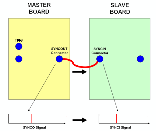
Synchronization -
Synchronization between two boards is done through the SYNCOUT and SYNCIN connectors. We call the signal sent through the SYNCOUT connector SYNCO and the signal sent through the SYNCIN connector SYNCI, so we do not confuse the connectors and the actual signals. For multiple board operation, there must always be one Master board. The Master board will send out the SYNCO signal through the SYNCOUT connector and the Slave boards will receive that signal through their SYNCIN connectors. Inside the Slave boards, the signal from SYNCIN is called SYNCI. The Slave SYNCI signals will always match the Master SYNCO signal.
When an armed master module receives a trigger signal, it generates a SYNCO signal to start the waveforms of itself and of the slave module. The SYNCO delay TT is about 1~3 μs and the waveform delays, TM and TS, are typically 128 ns and can be adjusted via the GUI or API-based applications. In applications, the slave waveform delay, TS, can be adjusted to compensate for the cable delay between interconnection of modules. To minimize delays between the trigger signal and waveform generation, the modules can be configured in slave mode and receive the trigger signal via their SYNCI's as shown in the following figure.
It is important to note that waveform generation starts ONLY based on the SYNCI signal (and only when module is in the "Triggered" state), even in the Master board or when in Standalone operation. The user may then wonder where does the Master board or the Standalone board receive its SYNCI signal? The SYNCI signal in the Master board, or when in standalone operation, mirrors the internally generated SYNCO signal.
Due to gating delays, there will be a slight difference between the SYNCI signals on each board. You can compensate for this difference by adjusting the Guard Length.
You may split the SYNCO signal to more than one slave board, but there can only be one Master board, and only the Master board requires a trigger signal.
The diagram below illustrates the signal timeline of a Master and Slave board. The board is assumed to already have been in the "Armed" state, where it remains until the TRIG signal falls and the board enters the "Triggered" state. Then, after the SYNCI/SYNCO signal rises, the board is in the "In Loop" state until it finishes running through the Loop Count parameter.
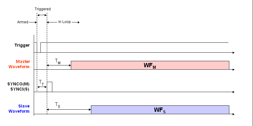
The trigger signal at the top can represent either the input at the
TRIG
SMA connector or a software trigger generated
by pressing the trigger button in the GUI toolbar. You must have a trigger to generate
the Master board's SYNCO signals.
Before the rising edge of the SYNCI signal, the board is considered to be in the “Triggered” state.
The SYNCI signal mirrors the SYNCO signal so both signals are always the same. The Slave board does not have a SYNCO signal. Since the SYNCO and the SYNCI signals are the same, for convenience we will use "SYNC" when referring to either of the signals.
TT
The delay between the falling edge of the TRIG signal and rising edge of the SYNCI/SYNCO signals is TT. It is typically 1-3 ?s.
When the SYNCI signal rises from logical level low to high, the board changes state from "Triggered" to "In Loop". Waveform output does not start immediately but is instead delayed for a brief time, TM for the Master board and TS for the Slave board(s).
TM
The delay between the rising edge of the SYNCI/SYNCO signals and the beginning of waveform output on the Master board is TM. It is typically 128 ns with the default Guard Length.
TS
The delay between the rising edge of the SYNCI/SYNCO signals and the beginning of waveform output on the Slave board(s) is TS. It is typically around 32 ns longer than TM, but can easily be shortened to match the Slave board waveform output with the Master board waveform output by shortening the Guard Length.
After the SYNC signals go back to low, the board will return to "Triggered" state when the waveform loop is completed if Auto Arm is enabled.