Board Layout -
The SYN101 board dimensions are 4 inches by 5 inches.
The module is manufactured from 4-layer sandwiched RO4003/FR4/RO4003 with a total thickness of 54 mils. The RF I/O’s are standard SMA connectors and the USB port is a type-B USB receptacle. Heat sinks are applied to both Direct Digital Synthesizers.
| Description | |
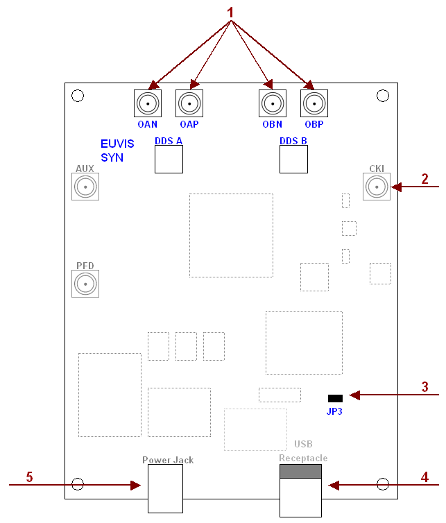
| 1 |
OAN / OAP / OBN / OBP (SMA)
SMA connectors for output waveforms. They should be connected to an oscilloscope and a spectrum analyzer. If only using one output, please terminate the unused output with a 50 ohm termination. OAN and OAP are outputs of "Channel A". OBN OBP are outputs of "CHANNEL B." |
| 2 |
CKI (SMA)
|
| 3 |
ROM Shunt (JP3)
For the SYN101, simply leave this shunt in place. |
| 4 |
USB receptacle
|
| 5 |
Power Jack
|