
General Description
The Euvis AWG474 module is a high-speed, dual-channel arbitrary waveform generator ideal for use in leading-edge applications. The AWG474 generates dual CW waveforms with sampling rates up to 4 GSPS. The on-board DRAMs provide up to 1G x 10-bit data memory to each channel. The deep memory provides long waveforms required for modern communications such as Orthogonal Frequency Division Multiplexing (OFDM). The high-speed clock input is single-ended 50-Ω terminated and accepts RF clock signals up to 4 GHz with a minimum power of +6 dBm. The AWG474 RF outputs are two pairs of differential analog outputs, with 50-Ω back termination. The module accepts a high-speed trigger signal and generates two programmable marker signals. The waveform generation can be operated in continuous, gate, or burst mode. The waveform contents can be dynamically changed using the user page selection. The AWG474 module can be controlled by a PC-based GUI via a high-speed USB 2.0 interface. The companion API provides an interface for software development.
Ordering and Pricing Information
For pricing information, please visit Pricing. For formal quotations, availabilities, and quantity-specific orders, please contact us
Key Features
- Two 10-bit DACs
- In-phase or quadrature synchronization of outputs
- Standard AWG has sampling rate of 4 GSPS with 4 GHz external clock
- Optional sampling rate range: 2 ~ 4 GSPS with 2 ~ 4 GHz external clock
- Up to 2 x 1G x 10-bit word memory depth with multi-page configuration
- Up to 0.25-second waveform at 4 GHz clock rate
- Accepts external trigger and generates marker signal (programmable)
- Programmable cyclic and burst repetitions
- USB 2.0 compliant interface
- 12V power supply
- User-friendly input data formats and various built-in waveforms
- Companion API and software drivers for easy system development
- API compatible with Matlab 2010a
- API compatible with LabView
- Multi-AWG synchronization
- Aluminum anodized enclosure: 8.25 x 3.5 x 10.7 (W x H x D) inches
Applications
The flexible Euvis deep-memory AWG module can generate arbitrary patterns with high sample rates, dynamic page selection, and continuous or burst mode operation which allows the AWG to be used for a variety of leading-edge applications, such as:
- Orthogonal Frequency Division Multiplexing (OFDM) transmitter
- Optical OFDM transmitter
- Ultra-Wideband transmitter
- Linear Frequency Modulation (LFM) and chirping
- Frequency Modulated Continuous-wave radar (FMCW)
- Electronic warfare
- VSAT satellite communications
- Test and measurement equipment
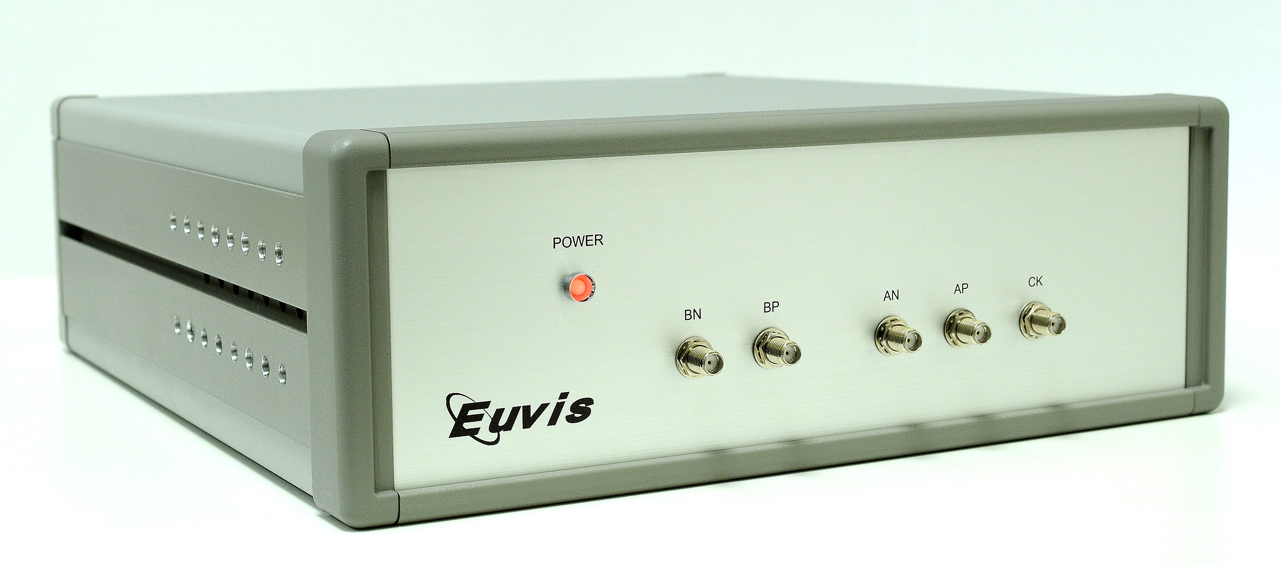
Module Photo:
Graphical User Interface

Functional Specifications
| GENERAL | |
| Amplitude Resolution | 10 bits |
| Running Modes |
Continuous
Gate Triggered Continuous Triggered Burst |
| User Interface |
USB API GUI for Windows XP and Windows 7 |
| INPUT CLOCK | |
| Type | Single Ended, 50-Ω terminated |
| Connector Type | SMA |
| Frequency Range |
Standard: 4 GHz
Optional: 2 GHz to 4 GHz |
| Power Level | +6 to +12 dBm (typical +9 dBm) |
| OUTPUT | |
| Type |
Dual channel
Each channel is differential, 50-Ω terminated |
| Connector Type | SMA |
| Output Rate |
Standard: 4 GSPS
Optional: 2 ~ 4 GSPS per channel |
| Output Level | -635 mV to 0 V |
| Output Power | -4 dBm to 0 dBm |
| Residual Phase Noise @ 10kHz from Carrier | -130 dBc/Hz |
| Output Return Loss | 15 dB |
| TRIGGER | |
| Connector | SMA |
| Source | External or Software |
| Recommended External Trigger | LVCMOS 2.5 V |
| WAVEFORMS | |
| Max Waveform Length | 1,073,725,440 samples per channel |
| Minimum Waveform Length | 64 samples |
| Shorter waveforms can be achieved by Null padding | |
| MARKERS | |
| Number of Markers | 2 |
| Marker 1 Level | LVCMOS 2.5V |
| Marker 2 Level | LVCMOS 2.5V |
| Marker Length | User defined |
| Minimum Marker Length | 32 samples |
| API | |
| Version | Euvis_Module_Compact_Core |
| CLR Language Support |
Visual C++
Visual C# Visual Basic Visual J# |
| Third Party Support | Compatible with Matlab 2010a and LabView |
| OPTIONS | |
|
Programmable profiles
Variable clock frequency for external clock (2 ~ 4 GHz) |
|
Electrical Specifications
| Parameter | Symbol | Min | Typical | Max | Unit |
| Output Level | Vout | -635 | 0 | mV | |
| Output Power | Pout | -4 | 0 | dBm | |
| Output Phase Noise | Nφ | -130 | dBc/Hz | ||
| Output Port Return Loss | RLRF | 15 | dB |
Multiple AWG's Synchronization:
Multiple AWG's can be operated to generate synchronized waveforms. The synchronization requires:
[1] All AWG's use the same clock source, or use clock sources phase-locked to each other. If the AWG internal clock is used, all AWG's must use the same reference clock.
[2] All AWG's must use the same trigger signal.
[3] The trigger signal is phased-locked (aligned) to the 1/32 clock.
[4] Fine adjustment can be done by specifying the delay in common parameters to further minimize the relative delay of AWG's outputs.
For details, please see synchronization.
Enclosure Information
| Enclosure Dimensions | |
| Length | 11 inches |
| Width | 10.5 inches |
| Height | 3.5 inches |
Enclosure Drawings
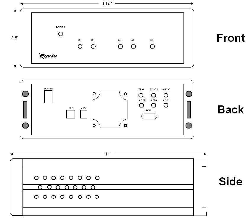
Top view with air flows
