
Multiple AWG's Synchronization
Multiple AWG’s can be synchronized with proper configurations. The key to synchronize all AWG’s is to
generate the trigger signals with the phase locked to the /32 clock. The AWG uses /32 clock to sense
the in-coming trigger. Waveform generations are based on the sensed trigger events. Therefore, the
sensed triggers of multiple AWG’s may bear different timing. To ensure all the AWG’s sense the trigger
in the same timing manner, the trigger signals must be synchronized (or phase locked) to /32 clock.
With external clocks, all the AWG’s should share the same clock or clocks with phase locked with respect to each other and share the same trigger as shown in Fig. 1. The trigger is phase locked to the /32 of the clock. An alternative configuration is to use SYNCO of AWG to lock the trigger. The SYNCO is /32 clock generated by the AWG. The configuration is shown Fig. 2.
Fig. 1 Multiple AWG's use the same clock source and a /32-clock locked trigger signal.

Fig. 2 Multiple AWG's use the same clock source and the same trigger signal, which is phase-locked to one of SYNCO's.
If internal clocks are used, all AWG SYNCI must use the same reference clock and the trigger should be phase-locked to one of the SYNCO of AWG’s as shown below.

Fig. 3 Multiple AWG's use the same reference clock and the same trigger signal, which is phase-locked to one of SYNCO's.
Once the trigger is locked to /32 clock, the relative delays of waveforms will be constant as shown in Fig. 4. The constant relative delays should be less than 32 clock periods. To further minimize the delays, users can use the Delay parameter, in the GUI under Common parameters as shown in Fig. 5, to adjust the delays of the waveforms. Delay value should be the relative delay of the current AWG and the last one (the AWG lags the most) and the unit of the delay is in data sample.

Fig. 4 Relative delay of two AWGs' waveforms. The delay should be less than 32 clocks.
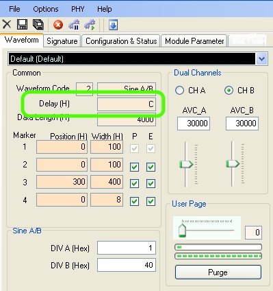
Fig. 5 Delay parameter in GUI.
Application note: Multiple AWG's Synchronization.